Minggu, 31 Maret 2013

Pine Sol to Clean Carburetors

I have a bunch of carburetor parts to clean and recently read that Pine-Sol did a great job. So I tested it. Looking at the ingredients, I see this stuff is 1.75% glycolic acid. It did go right through my nitrile gloves and I had to switch to some heavy duty ones. And I did wear my safety glasses.
These parts have been soaked about 30 minutes, lightly scrubbed with a toothbrush and wiped off and then soaked for another 30 minutes. Then another light going over with a toothbrush and rinse with cold water. The part on the left is before cleaning, on the right is after.


Wow! Pretty good.

Kamis, 07 Maret 2013

FMF Q4 Mod tested


Somewhere on the web I bumped into a great idea to modify the Q4 spark arrestor to reduce the sound.
So I bought an extra spark arrestor for $35 and tried it out.
The idea is that you cut some slots in the end of the arrestor and bend the tabs over the block the pipe a bit. I used duct tape to mark where I was going to cut:


Here are a few shots of the modified spark arrestor next to an unmodified one:


Results:
FMF Q4 with Spark Arrestor
RPM            Original          Modified
2000             87 dB                87 dB
6000             102 dB               102 dB (whistle sound noticed on modified)
8000             106 dB               106 dB

No improvement! Wow, I really expected this to work.  I guess I could bend the tabs down some more, but I don't want to crudely block the exhaust too much. I guess the lesson is that you need actual baffling, not just some blockage.

Another note is that these measurements with the original spark arrestor are different from the ones in my last post a couple days back. Just shows how variable this testing is.

Sabtu, 02 Maret 2013

FMF Q4 Muffler (slip on) vs the stock Arrow muffler on a Husqvarna TE250

I decided to try a FMF Q3 Muffler (#045338) on my 2010 Husqvarna TE250. The FMF Q4 is an aluminum muffler for which they claim a maximum of 96 dB. This information probably applies to the other 4 stroke Huskys with an Arrow exhaust for 2011 and 2012 too, like the TE310.

From the dealer, my Husky was pretty quiet, but it had the catalytic converter and the throttle stop then. If you follow the power up directions your remove both of those. And then the bike is really loud, with just the stock spark arrestor. But the power up directions also tell you to take the spark arrestor out and to put the baffle that comes in the kit in the pipe. This does make the bike a bit quieter.

So then you have a problem, if you like a quiet bike. First, with the stock kit baffle the bike still is pretty loud. Second, if you use the baffle, you don't have a spark arrestor.

“danbartol” on cafehusky did a bunch of research and testing on this. His comments are here:

Here are the stock Husky baffle options:

On the far right is the spark arrestor that comes with the bike. The middle baffle comes in the power up kit, and does quiet the bike down, but has no spark arrestor. (The baffle on the far left is a part you can buy from husky. It does quiet the bike down very nicely, but is very restrictive and still has no spark arrestor.)

I ended up welding a mesh screen on the end of the middle baffle (like Dan did), the one that came in the power up kit, and I've been running that. Here is a shot with the screen:

 But lately I've been going to some forests and have been concerned that the cobby mesh wouldn't pass muster. And I was hopeful that a Q4 from FMF might be quieter. And I also really like reducing my bikes weight, and the Q4 was likely lighter than the stock muffler.

The Q4 looks nicely blocked up inside, it's not a straight thru pipe:

Additionally, it comes with a spark arrestor that bolts in the end:


Weight comparison:
Stock Husqvarna with baffle: 113 oz (3204g) (baffle with tacked on screen weighs 5.2 oz or 156g)
FMF Q4: 91 oz (2576g) (Note FMF claims 6.1 pounds or 97.6 oz, maybe they count the hardware or something)
So the FMF is about 1.38 pounds lighter! That's cool.

Sound test:
Here was my setup. I roughly followed the AMA standard, by attempting to put the meter 20 inches at a 45 degree angle from the pipe. But my meter is a cheapo and this is not the right environment to test. All I was hoping to do was compare the two pipes. Note these tests are very rough, with me just trying to get the rpm right and then taking a quick look at the dB meter.

Stock pipe:


Q4:

Results:
Stock with baffle and custom on spark arrestor. Cat converter removed.
RPM            A weight           C weight
2000             88 dB                95 dB
6000             98 dB                103 dB
8000             104 dB               no test

FMF Q4 with spark arrestor
RPM            A weight           C weight
2000             92 dB                 98 dB
6000             101 dB               105 dB
8000             106 dB                no test

By ear, the FMF Q4 sounded deeper, with the volume approximately the same as the stock exhaust.

So essentially, my results were very similar to danbartol's. The benefit of the FMF Q4 is lighter weight and a certified spark arrestor. The Q4 is no quieter and maybe louder than the stock exhaust with the kit baffle. (Although by Dan's testing it's quieter than the stock exhaust fully uncorked with no spark arrestor or baffle. That makes sense to me.)

Final shot of the installed FMF Q4 on my TE250. The Pirie CF Pipe guard took some modification to get to fit. I also removed the FMF stickers as they don't pay me to run their pipe ;-)

Minggu, 06 Januari 2013

Spiegler Brake Lines and Leaking at the Crush Washers

Problem with Spiegler Lines leaking at the banjo bolts and crush washers.
I decided to put stainless steel braided brake lines on the GPz. I've done this on lots of bikes with great results. But it's definitely a job for a professional, don't mess with your brake lines unless you really know what you are doing.
In the past I have always used Galfer lines, but I'd heard good things about Spiegler and decided to try them.
Well... it ended up being a really hard project. The lines went on fine and bleeding was the normal big project. An important last step is to squeeze the brake lever very hard for several minutes and then to check the fittings for leaks: and my banjos were leaking! I double checked the torque specs and then tried a whole bunch of things to solve the leak, including over torquing the aluminum banjo bolts that Spiegler had provided. I searched the Internet and called Spiegler twice to confer. Nothing worked. Fluid leaked at the banjo bolt crush washers at several of the connections.
I was concerned about the aluminum banjo bolts. They where really cool, but you can stretch them and break them. I thought maybe they were stretching and not putting enough pressure on the washers. So I called Spiegler and ordered stainless steel banjo bolts and a bunch of new washers.
When the new bolts and washers arrived, it was a revelation... the new washers were different! I immediately called Spiegler back, and they confirmed the difference; they had gotten a bad batch of washers and I must have gotten them with my original shipment.
This picture shows the bad and good washer, and the obviously different profile.

 The thin washer is more easily crushed.
I could even feel the difference when tightening the banjo bolts with the good washers. When I tightened the banjo bolts with the bad washers my torque wrench quickly "clicked" but with the good washers I could feel the washer getting squished before I reached full torque.
And of course, with the good washers there were no leaks and the job was easily completed. Too bad I first wasted many hours with the bad washers.

Sabtu, 29 Desember 2012

Notes on installing a DVR2 on a Mondial 175TV


A friend asked me some questions about how I installed my DVR2 on my 1955 Mondial TV 175. I was about to email him and thought that this might make a somewhat interesting blog post. You can see it in the picture above installed in the recess under the gas tank. I had to make the black bracket shown.

I suggest running the bike with the original mechanical regulator first. That way you can verify that the bike does run and that the wiring is correct. Use a voltmeter to check the following:
  • Voltage at the battery with the battery unconnected
  • Voltage with the battery connected but with the ignition switch off. Should be the same as above.
  • Current from the battery connected but with the ignition switch off (should be zero!)
  • Voltage with the ignition switch on *and the points closed* but the bike not running. I get 3.5A with the "Spia" lamp on. This is the Spy lamp on the headlamp shell that tells you the ignition is on and the battery is not charging. If you remove this lamp the current should fall to 3A. (Thus my lamp draws 3.5 - 3 = 0.5A.)
  • Voltage and current with the ignition switch on *and the points open* but the bike not running. The only current flowing should be through the "Spia"; about 0.5A on my bike. If you remove the Spia lamp the current should fall to zero.
  • Voltage with the bike running at idle. The Spia lamp should go off at any higher RPM.
  • Voltage with the bike running at a higher RPM, maybe 3000. The Spia should be off.
(In all the above tests, when I say "with the ignition on", I am using the switch position that turns the ignition on but that DOES NOT light the headlamp or tailamp. On my bike this is the center switch position.)

These old mechanical regulators are often fairly crude in output and can overcharge a lead acid battery causing it to boil. They are adjustable, but are not very temperature stable. Note the vintage manual says the regulator should be set to 8.0 to 8.5 Volts with the battery removed! Additionally, many SLA / gel batteries have an internal fusible link, and that link can pop with overcharging causing permanent and total battery failure. Hence the interest in the modern DVR2 regulator that provides a nice constant 7.2 volts.

A Note:
As we are talking about the charging system, it is imaginable that someone playing with this on a Mondial 175TV might decide to remove the dynamo's armature while looking around. If you are going to do this it is critical to remember something.  The center bolt that retains the armature of the dynamo to the engine is REVERSE THREAD! If you ever need to remove the armature, remember the center bolt is loosened by turning it clockwise. I recommend leaving the armature in place as it can be delicate to remove!

So how to install the DVR2? It comes with a handy instruction sheet, but here are a few more tips. Remember this as a 6V installation.
Essentially all you have to do is:
  • Remove the battery from the bike for safety.
  • Connect the black ground wire on the DVR2 to a solid ground point. Remember that the gas tank may not be a good choice for that and painted screws can be a problem as well. Choose a good ground.
  • Connect the brown and white wires from the DVR2 together (because this is a 6V installation) and then connect that to the battery. This is the charging side of the circuit and would be a good place for a fuse.
  • Connect the yellow wire from the DVR to the +D of the dynamo.
  • Connect the ggeen wire to the Field of the dynamo.
  • Reconnect the battery .
Of course, it sounds a bit simpler than it is. Here is what I suggest.

1) Don't disconnect anything on the bike until you carefully document it. Label all wire ends (little strips of masking tape work well). And take pictures.

The underside of my original regulator looks like this:
You can see terminals are handily labeled F (for field), +D (for the positive output of the dynamo) and +B to the battery. When you remove the wires, label them like this.

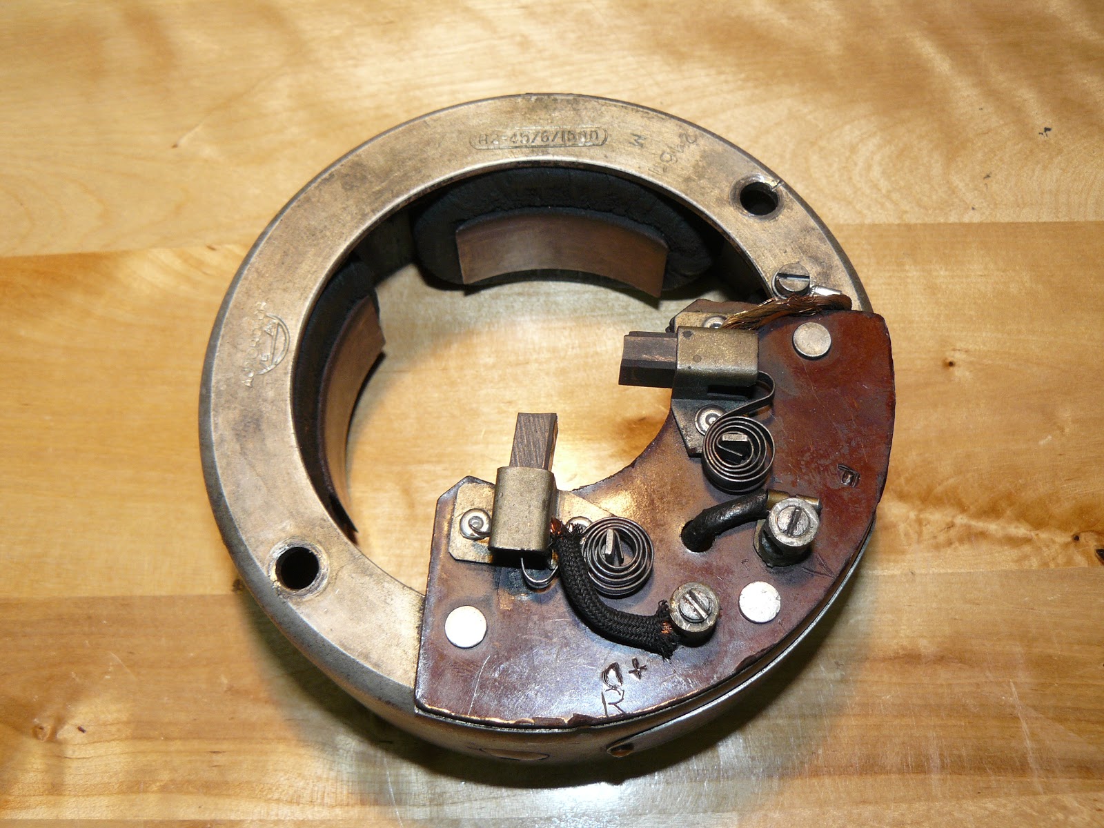
Now under the engine side cover, you can find the Dynamo. You will see this part, the stator, with terminals labeled +D and F.


And here is a crude schematic of the stator:


2) So up at the regulator: after you disconnect and label the wires, you should verify that they run to the proper terminals on the stator. Just temprorily disconnect the stator wires at the terminal, and check the resistance with your ohm meter.

3)  Check the wiring from the regulator B wire to the battery connector (remember your battery should be removed).

Note: Your original regulator may have multiple wires connected to the terminals of the old regulator. It is a good idea to investigate where those go as well. Consult your schematic and ohm the wires out.

4) Determine where you are going to connect the ground wire from the regulator. Remember that connecting it to the gas tank may be a bad idea, as the tank may have rummber mounts and painted mounting posts etc. I recommend running a wire where you connect the negative side of the battery to the frame.

5) Add fuses to the circuit as appropriate. I'm not an expert on this! But the idea is that if there is a short anywhere on your bike the fuse blows before anything is damaged. I rewired all of my Mondial so my wire colors are not the same as anyone elses. And I moved circuits as I wanted.  So don't look at my wiring diagram and expect it to be like yours! At any rate, on my diagram you can see I have three fuses. One fuse is on the battery, another fuse is on the +B side of the regulator and the last one is built into the headlamp switch and protects all of the lamps and headlamp, except for the Spia.
 
6) Now connect up the DVR2 I added a set of bullet connectors between the DVR2 and the wiring system of my bike. In this pic you can see the bullet connectors and the colors of the DVR wires and the colors of the wires on my bike. Note my bike wire colors will be different than yours!


And there you go. Add a bracket to hold the DVR2 to the tank and you are just about done.

7) As the last step I recommend running all the voltage and current tests you did at the beginning. Everything should be the same except for the voltages with the bike running. You should get a nice solid 7.2 Volts out of the DVR2 at any RPM.

Good Luck!
Carl


Kamis, 06 Desember 2012

Found this in my mesh oil screen

From my 2010 Husky TE250.
I had some trouble getting the mesh oil screen out of the bike... found it was hung up on some metal particles. Used a magnet to pull them out, so they are magnetic.


Man, I hope this isn't a significant problem. But these are more than a shaving. Almost look like parts from a tiny ring or washer...
Any ideas?
Carl


Well, this ended up being a disaster.
Ok, so here is my wrap-up. 5 weeks and $1100 later and my bike is back and ready for action. We found all the bearings and some of the cage bits under the right hand side cover. The rest of the bits were under the left cover stuck to the magnetic parts there. And there were a few bits crushed and wedged up against the crank bearing. Here a pic of my collection:


Here are my tips for the next person with this problem:

- Count your bearings. If you can find them all and most of the cage bits without splitting the cases... well some people might consider that good enough. If all you do is ride in the back yard on your farm, I might not split the cases. But we did find some bits in there. And its hard to flush them out. I ride in the desert and on trips far from home and a failure out in the field would really spoil a vacation (at the least). So I split the cases and looked.
- The replacement bearings from Husky look identical to the original. They are marked: "NSK 6901 INDONESIA". You might do some research to see if you can get something that is *known* to be better. I'm hoping my originals just were from a bad batch.
- There is a chance that this gear and bearing could be replaced fairly easily during a valve adjustment. I might consider upgrading/replacing the bearings at that time.
- The bearings were $15 and the gear was $22. The parts are cheap.
- Don't ignore and metal pieces in your oil! If you find anything check that top timing gear's bearings. Maybe you can catch it before it falls apart.
Carl

Selasa, 27 November 2012

GPz550 Caliper Rebuild

This is a followup to my earlier post on disassembling the calipers.


I used a white scotchbrite pad (the mildest version) to clean up the bore. While the piston rides on the seal, it's still important not to mark up the bore with an abrasive. There was lots of crud inside the bore so this took quite a lot of time to get done right. Also I ended up using a pick to help clean up the grooves that hold the seals.
Here's a good shot of the bore after cleaning. While I removed all the corrosion there remained some marks from where the corrosion was. I hope that's OK, but it has to be better than it was! I'd suggest showing this to a real mechanic if you try to do this yourself.


 This pistons actually looked good. One had the tiniest scratch on it so I bought new pistons and the new ones where scratched worse! So I returned them and just polished up the old pistons. Here is the ready to go piston.


 And both calipers ready to assemble.


There is much debate online on weather to use brake fluid or brake caliper grease to lubricate the parts before assembly. Those who dislike using brake fluid claim getting any of it outside the caliper seals is a bad thing as it attracts water and corrosion. They advocate grease as it preserves the rubber and keeps water out. Those who dislike caliper grease claim it could contaminate the brake fluid. I chose to use brake fluid because that is what the Kawasaki shop manual recommended.

Now the hard part. There is a trick to reassembly and I did a bunch of web searching to determine how to do this. You have to put the seal in the bore first. Then the hard part, the dust seal/cover. That seal needs to be put on the inside end piston first! Like this:


Then you carefully insert the outside of the seal into the bore's groove while holding the piston just outside of the bore. I started in the back like this:


Note the piston is not yet in the bore! Its just above it.
Then work the rest of the seal into the groove. Eventually just the front remained out.


And I used a tool to delicately push the remaining seal down into the groove. Being very, very careful not to damage the seal. This is a shot with the dust seal completely in the groove and on the piston, but the piston is still just sitting on top of the bore.


Now you carefully push the piston down making sure it remains straight to the bore. This should be done by hand! Once it started to go through it just zoomed by the seem all the way down the bore. I wish I had controlled it better as It happened so fast when it went in that I didn't get a chance to carefully put the seal in the piston groove, it appeared to just land in there by itself. Regardless, it looks good to me.


Unless you are very confident in your skills I'd leave this project to a professional mechanic.

Regarding the master cylinder, I determined that was shot. The bore was very corroded and you can't hone an aluminum master cylinder. If you do, you destroy the finish and the bore will chew up the rubber piston seal. So I bought a new master cylinder, being careful to get one with the same bore and leverage as the original.

Now, onward to assembly!